
Flexible Transmission Column Lift
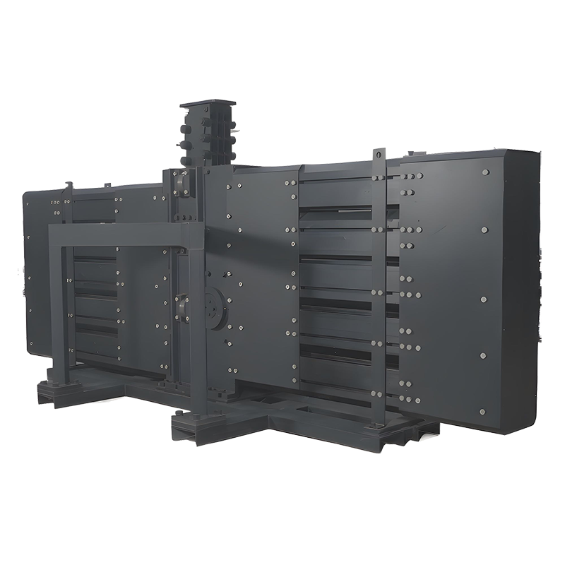
Column Lift is an ideal solution for applications requiring a shallow pit and long stroke, making it well-suited for lifting in specialized production lines.
It serves as a superior alternative to traditional scissor lifts, lead screws, hydraulic cylinders, flexible gears and large spirals. With its high-quality, reliable transmission, the Column Lift opens up new possibilities in fields that demand precision and durability.
Column Lift offers the following main features:
1.It converts a horizontally moving chain link into vertical movement via a drive housing, enabling vertical lifting.
2.The flexible chain link is transformed into a unidirectionally stiff structure, with rigid chain links connected by movable hinges to form a vertical, load-bearing column.
3.It provides stable operation, high reliability, long service life, low maintenance costs, and high repeatability. The Column Lift also offers flexible configurations, easy installation, and suitability for heavy loads (up to a 60-ton dynamic load and a 90-ton static load per unit). It requires only a shallow pit and supports a large stroke length, reaching up to 16 meters or more.
Application Scope:
Column Lift is an ideal solution for applications requiring a shallow pit and long stroke, making it well-suited for lifting in specialized production lines. It serves as a superior alternative to traditional scissor lifts, lead screws, hydraulic cylinders, flexible gears and large spirals. With its high-quality, reliable transmission, the Column Lift opens up new possibilities in fields that demand precision and durability.
Column Lift Composition and Structure:
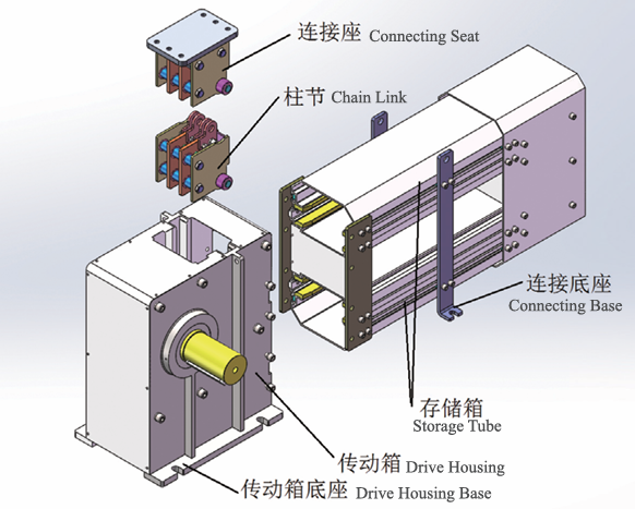
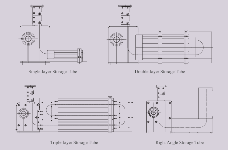
Column Lift is composed of a chain link connecting seat, chain links, a drive housing, and a storage tube. Storage tubes are available in various configurations, including single-layer, double-layer, right-angle, and three-layer designs. Right-angle and three-layer storage tubes can also be combined with single-layer or double-layer tubes for added versatility.
Technical Specifications:
● Speed: max speed 0.30m/s, Refer to specific model parameters for details.
● Perpendicularity requirement: ±1mm/m if S<=1m
±1mm/m and ±2mm over full travel if 1m<S<2m
±1mm/m and ±3mm over full travel if S>2m
● Transmission efficiency: 0.78 ~ 0.85
● Noise level: <35-50 dB at 0.10m/s (measured 1m away)
● Repeat positioning accuracy: within ±1 mm
● Acceleration: up to 0.3m/s2
Transmission Geometric Parameters:
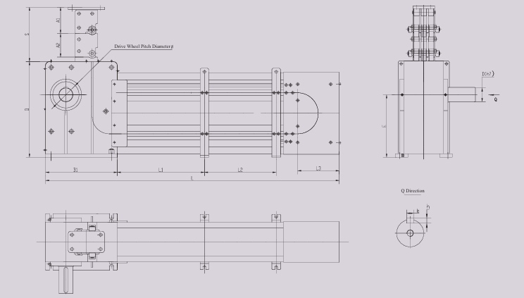
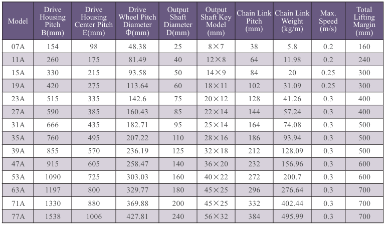
Note: The weights listed in the table are for reference only when selecting models and may vary from the actual weight indicated on the label.
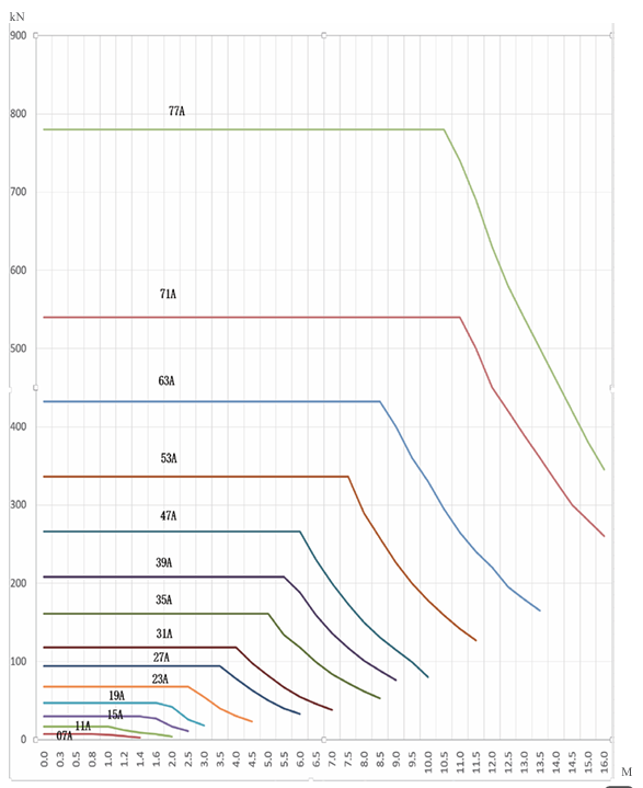
Pitch of Chain Link-Dynamic Load Parameter (with guiding system):
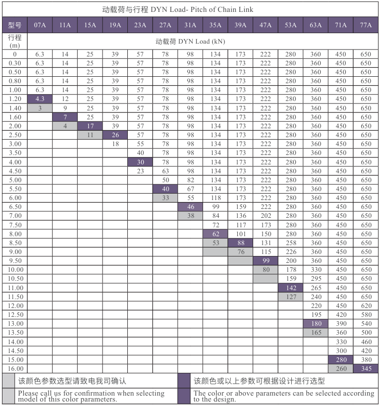
Note:1.Total length of chain link = stroke + lifting margin.
2.To minimize vibration, insert a rubber pad between the chain link connecting seat and the structural body. The rubber pad should match the thickness of the chain link connecting plate.
3.The table values are for reference in model selection. If the guiding system is stable and secure, the stroke and load can be adjusted upward within the maximum load capacity.
Pitch of Chain Link-Dynamic Load Curve:
Pitch of Chain Link-Static Load Parameter (with guiding system):
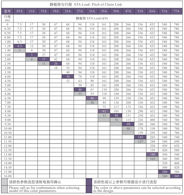
Note:1.Total length of chain link = stroke + lifting margin.
2. To minimize vibration, insert a rubber pad between the chain link connecting seat and the structural body. The rubber pad should match the thickness of the chain link connecting plate.
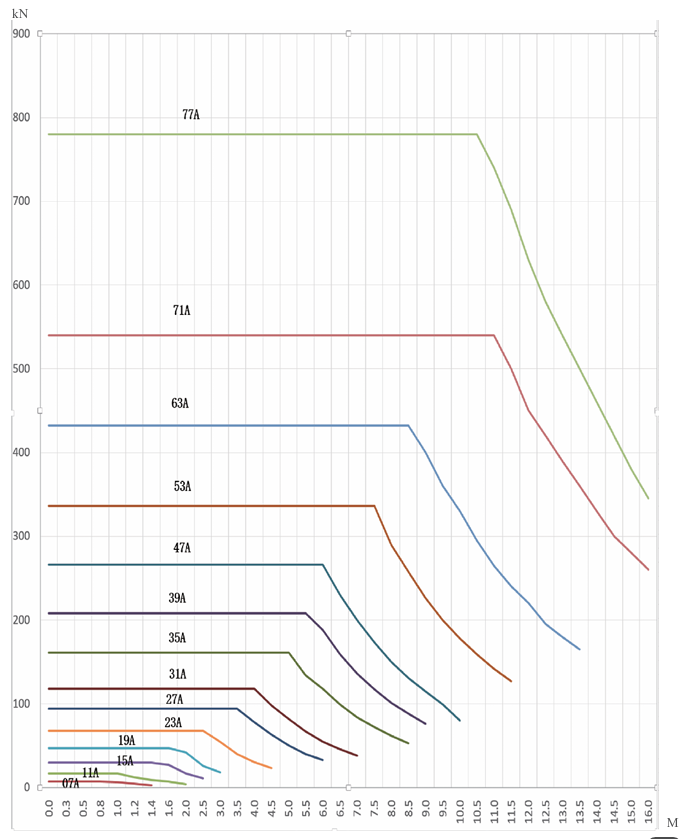
3.The table values are for reference in model selection. If the guiding system is stable and secure, the stroke and load can be adjusted upward within the maximum load capacity.
Pitch of Chain Link-Static Load Curve:
Instructions for Model Selection:

Operation Requirements:
 * Installation personnel must comply with the installation parameters and performance requirements specified for Column Lift.
* The parameters, load, stroke and speed should not exceed those specified for Column Lift selected.
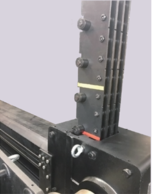
* When Column Lift reaches its lowest position, the connecting seat should not be in contact with the upper surface of drive housing. When reaching the warning line of Column Lift - the yellow line - it must slow down. When reaching the maximum stroke it should not exceed the red line (stop line) marked on Column Lift, as shown in the diagram on the right.
* Any maintenance work should be carried out by a qualified technician.
* Any removed safety devices must be reinstalled in the lifting system before resuming restarts.
* Limit switch and extreme limit switch must be installed before operation to avoid accidents caused by operating errors.
* Before operation, a sufficiently strong lifting guide system must be installed.
* Column Lift does not allow direct lifting of personnel. Please call us for confirmation, if you have special requirements.
Lifting &Installation:
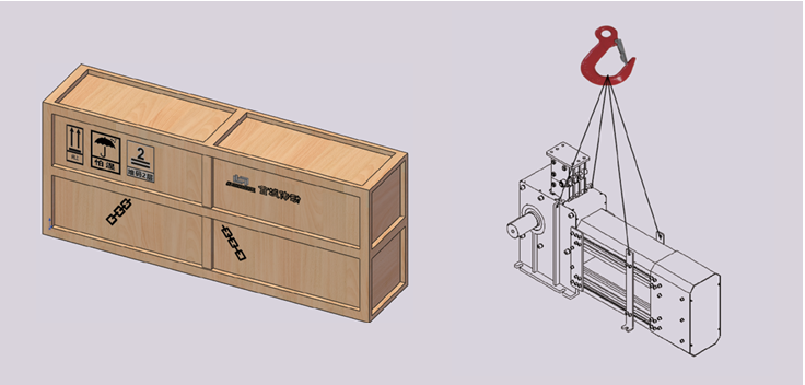
Attention should be paid to the following situations when lifting and hoisting.
* Before lifting, find the correct direction for the packing case and lay it flat, then unpack it.
* Balanced lifting at four points shall be obeyed while two-point lifting is strictly prohibited.
In order to ensure the stability and optimized performance of Column Lift, the following requirements must be followed during:
● Add a rubber between the chain link connecting seat and the structural body, with a thickness equivalent to that of the chain link connecting seat connecting plate.
● The top mounting plate must be rigidly attached to the lifting platform. The bolt grade for the attachment position of the column joint attachment seat to the structure is grade 8.8. Rotating accessories are not provided under normal circumstances (please call for inquiries due to special needs).
● The drive housing must be firmly attached to the base without any gaps and must be parallel to the top mounting plate inthe horizontal direction. The bolt grade of connecting the driving case to the ground structure is 8.8.
● The bolt grade of connecting storage tube to the ground structure shall not be less than 4.8.
● The transmission path of the load must be vertical and parallel to Column Lift.
● Horizontal alignment of drive housing: use the top of the drive housing as a benchmark, with a tolerance of less than 0.5mm.
● Vertical alignment of Column Lift: use the circular surface of chain link guide roller and the side of the chain link plate as the benchmark to check the verticality and torsion.
● Perpendicularity. 1) ±1mm/m if S<=1m 2) ±1mm/m, ±2mm/full travel if 1m<S±1mm/m, ±3mm/full travel if S>2m
● Cover and protect Column Lift and drive housing during equipment installation to avoid the entry of other objects or contamination.
● The lifting platform must be equipped with a guiding system that is consistent with the direction of Column Lift, and horizontal movement is not allowed.
● Column Lift is assembled by chain link through shafts. All components and parts are pre-lubricated for corrosion resistance.
● To prevent the sundries from falling into drive housing, the rollers in the chain link can be lubricated with heavy duty gear oil. Lubricating grease is not recommended. A small amount of grease can be added to the roller chain for lubrication under good working conditions
● Column Lift is an unidirectional rigid body and installation must avoid danger from appearing as shown in the picture below.
● During powered on trial operation, use low speed and jogging to confirm the operation direction. Adjust the upper travel limit switch to the lowest position, the down travel switch to the highest position, and gradually adjust the travel switch to the correct position after smooth operation. When adjusting the lower limit, do not exceed the red warning line at the end of the chain link.
● When chain link connecting seat is lowered to the lowest position, sufficient buffer space is reserved between connecting seat and the roller chain drive housing. When chain link connecting seat rises to the highest position, sufficient margin should also be left. The faster the speed, the more margin should be reserved to ensure the safe operation of Column Lift.
● In order to ensure the safe operation of Column Lift, a safety travel switch for protection must be installed before operation. It is recommended that the safety travel switch signal should be fed back to the control system and displayed.
● Column Lift cannot bear large horizontal loads, and equipment such as elevators or lifting platforms must be equipped with sufficiently strong guiding systems, such as guide rails, scissor-truss and guiding columns, when subjected to lateral loads.
● When installing multiple sets of Column Lift, priority should be given to symmetrical installation, which helps to ensure the overall stability of the elevator or lifting platform.

Maintenance:
* After multiple trial runs of Column Lift, the verticality of lift needs to be adjusted to ensure that chain link enters the drive housing normally, Regularly inspect according to operation and usage, and the
inspection method is the same as the vertical alignment method during installation.
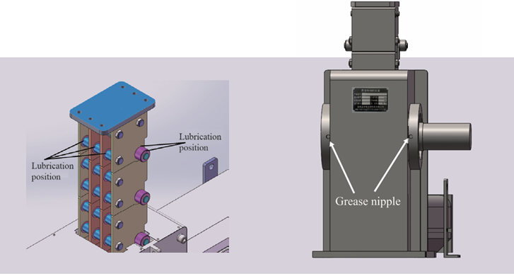
* Column Lift is lubricated with a small amount of heavy duty gear oil and the chain link surface and rollers and roller sleeves are applied with oil for lubrication and rust prevention. See picture below on the left.
*After a total of 500 hours of operation,add lubricating grease to the oil nozzle of driving case(3# lithium grease). See picture below on the right.
* Check the verticality of Column Lift every 3 months to ensure that it is within the range of use.
* Check the tightness of bolts and other fasteners.
Technical Parameters Required for Ordering:
We will carefully study each inquiry and order to ensure that the lifting system provided by us fully meet clients' requirements.Please provide the following information: lifting platform dimensions,effective stroke, stroke allowance, static load,dynamic load,lifting platform deadweight, speed, pit depth, acceleration and deceleration, etc
Rigid Column Lift (hereinafter referred to as RCL)
Column Lift is an ideal solution for applications requiring a shallow pit and long stroke, making it well-suited for lifting in specialized production lines.
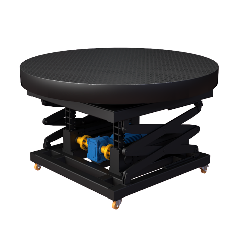
It consists of a motor, a reducer, a flexible column, a linear guide, a scissor support guide frame, a base frame, a rotating mechanism, a table, etc.
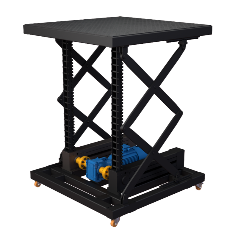
It consists of a motor, a reducer, a flexible column, a linear guide, a scissor support guide frame, a base frame, a table, etc.
*Note: Please make sure to fill in the information accurately and maintain smooth communication. We will contact you as soon as possible

